In some installations, there's only a limited amount of supply power available for chargers. For example a 3x35A power supply cannot feed double socket outlet charger, like Chago Pro EVF200 with full charging current (2x 3x32A). Or for example parking area has 50 chargers that need to share 3x800 Amperes but no static current limit is wanted to be configured as it would limit all the chargers to 3x16A. In such cases the maximum charging current for each charging EV can be adjusted with a scheme that ensures that maximum available current is given to EVs being charged in all situations and still not go over the maximum electric supply capacity limit in Amperes (A).
Introducing Advanced Dynamic Load Management
The Ensto Chago chargers with CC1612 charge controller have Advanced Dynamic Load Management (DLM) since 4.2 firmware version. Please use Advanced DLM instead of the old Peer Group, which will be phased out.
Terminology
MAXCUR = Maximum current not to be exceeded by charging system
DLM Master = One CC1612 charge controller is promoted as DLM Master. It knows the MAXCUR. Typically one CC1612 charge controller is selected as DLM Master and DLM Slave at the same time.
DLM Slave = Other CC1612 charge controllers are DLM Slaves. They connect to DLM Master.
DLM Group = One DLM Master and one or more DLM Slaves form a group under which the MAXCUR is not exceeded.
OCPP Master = In double sided chargers with two outlets, the master controller (left hand side controller) is the OCPP Master, it handles the communication towards OCPP back-end and has OCPP Connector Id 1. OCPP Master is independent of the DLM Master.
OCPP Slave = In double sided chargers with two outlets, the slave controller (right hand side controller) is the OCPP Slave. It uses OCPP Master to communicate with OCPP back-end and has OCPP Connector Id 2. OCPP Slave is independent of the DLM Slave.
Operating principle
One DLM Master charger and one or more DLM Slave chargers create a DLM group. The DLM Master of the group knows (is set) the maximum charging current (MAXCUR) that must not be exceeded. DLM Slave obeys and sets charging Amperes to a charging EV as the DLM Master commands it to do. If charging situation changes in any of the DLM Slaves, the the DLM slave communicates the change to the DLM Master that then adjusts a new maximum current (A) to every DLM Slave.
If communication between the DLM Master and the DLM Slaves is lost then both parties adjust to configured minimum current (for example 6A or even pause charging temprorarily) to not go over the maximum current (MAXCUR) limit in any situation.
DLM is also phase aware, so three EVs with 16A one phase on-board chargers, each charging from different phases due to phase rotation being applied to the charging infrastructure, only consume 3x16A of the capacity allowing other charging EVs to draw more amps. To get advantage of phase rotation follow these instructions: Phase Rotation
More Advanced DLM schemes are to be coming later in firmware versions, like VIP user privileges, first-in-first-out and so on.
There are 4 different algorithm stages for reaching the DLM goal (to not exceed a certain max overall limit) as follows:
Stage 1 uses HW limits (so no DLM limit at all)
Stage 2 uses potentially signaled current
Stage 3 uses actual charging current
Stage 2 is used if stage 1 is not able to reach the goal
Stage 3 is used if stage 2 is not able to reach the goal
And so on...
Stage 4 uses the minimum current limit
Note: the minimum current limit is a software configuration parameter and this amount of current is guaranteed to be available to the car (from the socket/controller board where this value is set), so same amount of current must be reserved from the main fuse pool, as the load adjustment does not go lower than this value. Therefore 6A (minimum to start charging based on standard 61851) is a good default value.
Physical connection
DLM Master and DLM Slaves must be accessible to each others in the same IP-network. Connect the chargers to the same Ethernet network, see picture below:
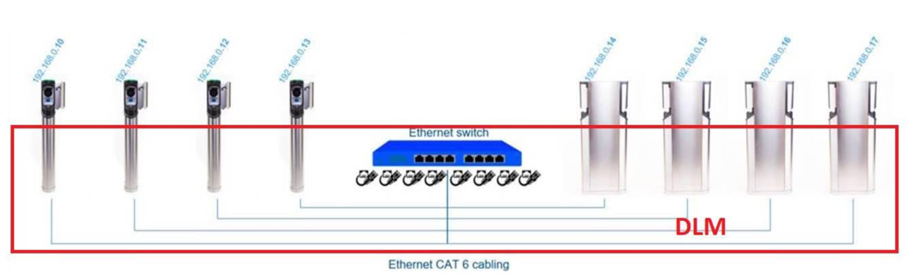
By factory default the chargers are using dynamic IP-addresses (DHCP = the router gives IP-address to the chargers automatically), but if DHCP is not in use then static IP-addresses must be set to the chargers. DLM uses IP port 1666.
Configuration in web UI 1.0
DLM configuration must be done to both DLM Master and DLM Slave charge controllers separately using the CC1612's web config page.
Selecting DLM Master and DLM Slave roles:
- Select one charger's OCPP Master controller as DLM Master.
- All other chargers' OCPP Master and OCPP Slave controllers are DLM Slaves.
Do the below steps in the DLM Master:
- Login to the Operator page of the Master controller: Connect laptop to controller
- Search for Dynamic Load Management field and select DLM Master (With internal DLM-Slave).
- Set maximum input supply electricity current level in field Overall current limit Phase 1. Note: unbalanced phase loads are supported so set other phases too. Also be noted that phase rotation is supported so be sure that each chargers supply cable order is as it is set in the field Phase rotation of the ChargePoint.
- Set maximum input supply electricity current level in field Overall current limit Phase 2.
- Set maximum input supply electricity current level in field Overall current limit Phase 3.
- New firmwares has EVSE Sub-Distribution Limit (L1/L2/L3) [A] and Operator EVSE Sub-Distribution Limit (L1/L2/L3) [A] that needs to be set.

- Click Save & Restart at the bottom of the page.
Do the below steps in all the DLM Slave(s):
- Login to the Operator page of the Slave controller: Connect laptop to controller
- Search for Dynamic Load Management field and select DLM Slave (Master-Auto-Discovery).

- Click Save & Restart at the bottom of the page.
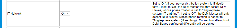
Note: If you have IT-network (grid without neutral line), then you must select also IT-network on DLM Master starting from 4.63 firmware version.
Example case:
Dual sided charger with 3*32A supply cable capacity is divided to each side of the charger:
DLM Master side:
DLM Master (With internal DLM-Slave).
EVSE Sub-Distribution Limit (L1/L2/L3) [A]: 32 for all three phases
Operator EVSE Sub-Distribution Limit (L1/L2/L3) [A]: 32 for all three phases
Minimum Current Limit [A]: 16
Disconnected Limit [A]: 16
DLM Slave side:
DLM Slave (Master-Auto-Discovery).
Minimum Current Limit [A]: 16
Disconnected Limit [A]: 16
Result: We can guarantee that each charger socket can charge 16Amps in case of both sockets are occupied, but if only one side is occupied then that one socket get 32A. Also in case of DLM master-slave communication is disconnected then each side get 16A. 32Amps main fuse never blows. Operator current limit must be set separately to 32Amps in Master side and Slave side too. The charging standard state that minimum current is 8Amps, so that is limiting maximum numbers of the charging points per electricity supply capacity i.e. 80Amps fuse / 8Amps = 10 charging sockets is maximum amount from 80Apms supply.
Level 2 DLM with external meter
By installing an additional electricity meter (like to the building supply main fuse, or distribution segment transformer, or any unknown load that is part/branch/join of EV charging load) it is possible to adjust charger or charger group total load based on additional electricity meter reading. Set External Meter Support ON in DLM Master configuration parameter:
Supported meter types:
(0)eHZ Meter
(1)S0 Meter Opto 1
(2)S0 Meter Opto 2
(3)No Meter
(4)S0 Meter Dedicated Input
(5)Internal Meter
(6)Modbus Meter ABB
(7)Modbus Meter Eastron SDM630
(8)Modbus Eastron SDM120_220
(9)Modbus Meter Garo GNM3D
(10)Modbus Meter Garo GNM1D
(11)Modbus Meter Garo GM3T
(12)Modbus Meter Garo EM270
(13)Modbus Meter Finder
(14)Modbus Saia ALE3
(15)Modbus Inepro PRO1_2
(16)Modbus Inepro PRO380
(17)Modbus Optec
(18)Modbus NZR EcoCount S85
(19)Modbus B-Control EM300-LR
(20)Modbus Meter Carlo Gavazzi EM200
(21)Modbus Meter Carlo Gavazzi EM340
(22)Modbus Meter Garo GNM3T
(23)Modbus IME CE4DMID31
(24)Modbus Siemens 7KT1666
(25)Modbus B-Control EM300-LR (TCP)
(26)Modbus Siemens 7KM2200 (TCP)
(27)Modbus Phoenix Contact EEM-MB371 (TCP)
(28)Modbus Schneider iEM3555
Def:No Meter
When chosen eHZ, then meter is connected to EHZ connectors on the controller board.
When chosen Modbus, then meter is connected to RS485A and RS485B connectors on the controller board and Modbus device address of the meter is set as 2 in settings inside of the meter.
When chosen S0, then meter is connected to S0 Data and S0 Power connectors on the controller board.
Starting from firmware version 4.60 also following Modbus over TCP/IP meters are supported:
B-Control EM300-LR (TCP)
Siemens 7KM2200 (TCP)
When chosen TCP/IP -meter, then meter is connected to the Ethernet -connector on the controller board or in bigger installations with Ethernet switch to Local Area Network (LAN).
See connector label markings on the controller printed circuit board.
Configuration in web UI 2.0
DLM configuration must be done to both DLM Master and DLM Slave charge controllers separately using the CC1612's web config page.
Selecting DLM Master and DLM Slave roles:
- Select one charger's OCPP Master controller as DLM Master.
- All other chargers' OCPP Master and OCPP Slave controllers are DLM Slaves.
Do the below steps in the DLM Master:
- Login to the Operator page of the Master controller: Connect laptop to controller
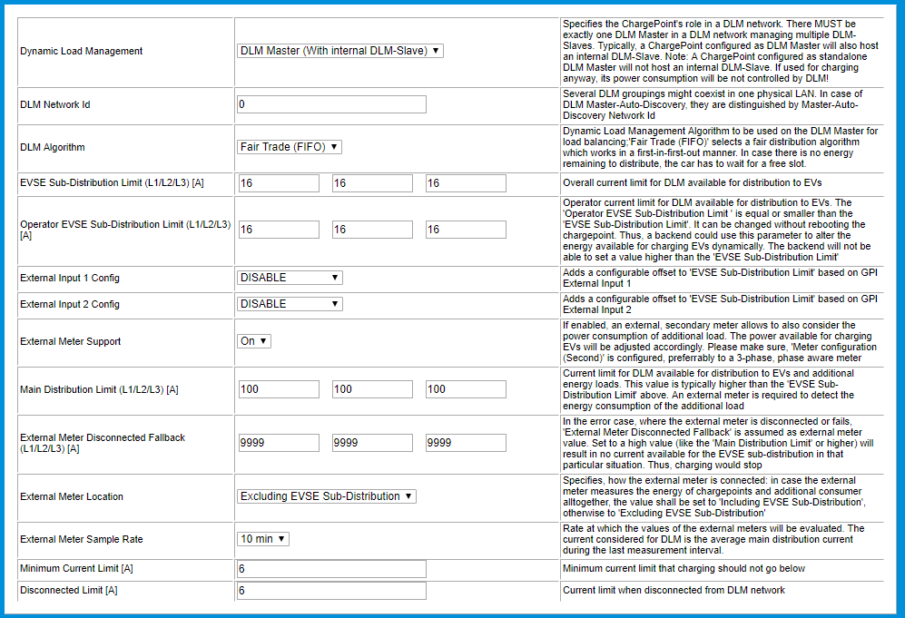
- Search for Dynamic Load Management field and select DLM Master (With internal DLM-Slave).
- Set maximum input supply electricity current level in field Overall current limit Phase 1. Note: unbalanced phase loads are supported so set other phases too. Also be noted that phase rotation is supported so be sure that each chargers supply cable order is as it is set in the field Phase rotation of the ChargePoint.
- Set maximum input supply electricity current level in field Overall current limit Phase 2.
- Set maximum input supply electricity current level in field Overall current limit Phase 3.
- New firmwares has EVSE Sub-Distribution Limit (L1/L2/L3) [A] and Operator EVSE Sub-Distribution Limit (L1/L2/L3) [A] that needs to be set.

- Click Save & Restart at the bottom of the page.
Do the below steps in all the DLM Slave(s):
- Login to the Operator page of the Slave controller: Connect laptop to controller
- Search for Dynamic Load Management field and select DLM Slave (Master-Auto-Discovery) and DLM Network ID (that match with DLM master's DLM Network ID) if dynamic IP-address (DHCP) is in use in Ethernet network or set static/fixed IP-address of the DLM Master. In the following picture static/fixed IP-address is in use in the Ethernet network:

- Click Save & Restart at the bottom of the page.
Note: If you have IT-network (grid without neutral line), then you must select also IT-network on DLM Master starting from 4.63 firmware version.

Example case:
Dual sided charger with 3*32A supply cable capacity is divided to each side of the charger:
DLM Master side:
DLM Master (With internal DLM-Slave).
EVSE Sub-Distribution Limit (L1/L2/L3) [A]: 32 for all three phases
Operator EVSE Sub-Distribution Limit (L1/L2/L3) [A]: 32 for all three phases
Minimum Current Limit [A]: 16
Disconnected Limit [A]: 16
DLM Slave side:
DLM Slave (Master-Auto-Discovery).
Minimum Current Limit [A]: 16
Disconnected Limit [A]: 16
Result: We can guarantee that each charger socket can charge 16Amps in case of both sockets are occupied, but if only one side is occupied then that one socket get 32A. Also in case of DLM master-slave communication is disconnected then each side get 16A. 32Amps main fuse never blows. Operator current limit must be set separately to 32Amps in Master side and Slave side too. The charging standard state that minimum current is 8Amps, so that is limiting maximum numbers of the charging points per electricity supply capacity i.e. 80Amps fuse / 8Amps = 10 charging sockets is maximum amount from 80Apms supply.
Level 2 DLM with external meter
By installing an additional electricity meter (like to the building supply main fuse, or distribution segment transformer, or any unknown load that is part/branch/join of EV charging load) it is possible to adjust charger or charger group total load based on additional electricity meter reading. Set External Meter Support ON in DLM Master configuration parameter:

Supported meter types:
(1) S0 Meter 'Opto 1 In'
(2) S0 Meter 'Opto 2 In'
(3) No Meter
(6) Modbus Meter ABB
(7) Modbus Meter Eastron SDM630
(8) Modbus Eastron SDM120_220
(9) Modbus Meter Garo GNM3D
(10) Modbus Meter Garo GNM1D
(11) Modbus Meter Garo GM3T
(12) Modbus Meter Garo EM270
(13) Modbus Meter Finder
(14) Modbus Saia ALE3
(15) Modbus Inepro PRO1_2
(16) Modbus Inepro PRO380
(17) Modbus Optec
(19) Modbus TQ EM300-LR
(20) Modbus Meter Carlo Gavazzi EM200
(21) Modbus Meter Carlo Gavazzi EM340
(22) Modbus Meter Garo GNM3T
(23) Modbus IME CE4DMID31
(24) Modbus Siemens 7KT1666
(27) Modbus Hager ECR380D
(28) Modbus Meter Garo GNM3TD
(29) Modbus Meter Carlo Gavazzi EM210
(31) Modbus Schneider iEM3555
(32) Modbus ECS M3PRO
(33) Modbus Janitza UMG 512/96 PRO
(35) Modbus Janitza UMG 605 PRO
(37) Modbus DZG DVH4013
(38) Modbus Gossen Metrawatt EM2289
(39) Modbus Eastron SDM72D
(40) Modbus Iskra WM3M6
(41) Modbus TQ EM410/EM420
(43) Modbus Berg BME 461
(44) Modbus Berg B23
(45) Modbus Phoenix Contact EEM-EM357
(47) Modbus ABB EV3(72) eHZ Meter via USB
(49) Modbus YTL DTS353F
(50) EV Optimizer
(53) Modbus SELEC EM2M-1P-C-100A
(55) Modbus Lovato DMED 301
(56) Modbus Eetarp GEM630
(57) Modbus Eetarp GEM230
(58) Modbus Eastron SDM230
(60) ER Eastron SDM630-EV
(61) ER NZR EcoCount SL+SC 85
(62) ER Iskra WM3M4C
(63) ER NZR EcoCount SL+S 85
(64) Modbus NZR EcoCount S85/SL85
(65) Modbus DZG DWH4113
(66) Modbus ABB D1M
(68) Modbus Eastron SDM72D-M-V2
(70) ER EMH iML
(71) Modbus Eichrecht
(74) eHZ-B Meter via USB
(77) Modbus Iskra IE38M
(78) Modbus Meter Finder 7M38
(79) Modbus Meter Garo GMI3D-LP
(81) Modbus Schneider Generic
(83) Modbus Wago 879-3000
(85) Modbus Meter Carlo Gavazzi EM111/112
(86) Modbus IME CE4DF3DTMID
When chosen eHZ, then meter is connected to EHZ connectors on the controller board.
When chosen Modbus, then meter is connected to RS485A and RS485B connectors on the controller board and Modbus device address of the meter is set as 2 in settings inside of the meter.
When chosen S0, then meter is connected to S0 Data and S0 Power connectors on the controller board.
Starting from firmware version 4.60 also following Modbus over TCP/IP meters are supported:
(25) Modbus TQ EM300-LR (TCP)
(26) Modbus Siemens 7KM2200 (TCP)
(30) Modbus Phoenix Contact EEM-MB371 (TCP)
(34) Modbus Janitza UMG 512/96 PRO (TCP)
(36) Modbus Janitza UMG 605 PRO (TCP)
(42) Modbus TQ EM410/EM420 (TCP)
(54) Modbus ECS M3PRO (TCP)
(67) Modbus ABB D1M (TCP)
(80) Modbus IPD Control (TCP)
(82) Modbus Schneider Generic (TCP)
(84) Modbus Janitza UMG 604 PRO (TCP)
When chosen TCP/IP -meter, then meter is connected to the Ethernet -connector on the controller board or in bigger installations with Ethernet switch to Local Area Network (LAN).
See connector label markings on the controller printed circuit board.
Related Articles